Oscillation itself is the production of a certain type of ‘wave’, which produces a different sound depending on the shape of the wave. At higher pitches the oscillator we’ll make creates a constant note, at lower pitches you will hear a more ‘crackled’ sound. The wave we’ll make in this tutorial is a pulse wave (starting as a square wave which can be varied later).
Build your first breadboard synthesizer: an oscillator
- Square Wave – looks like a square, and makes a reedy, hollow sound
- Pulse Wave – a variation on the above, the pulse wave is half as wide as a square wave
- Other common waves include: Triangle Wave, Saw Wave, Sine Wave
What you will need (electronic components available from rapidonline.co.uk):
- 1x breadboard – this is what you will put the components and wires in to make the circuit (available here or here)
- 1 x CD40106 chip (it’s called a ‘hex schmitt trigger’ integrated circuit) – make sure it is a ‘DIP’ style chip because this will have pins suitable for breadboards (available here)
- Capacitors: 1 x 0.1uF (small brown with 104 printed on it) available here
- Resistors: 100k resistor (you could try different value resistors for different ‘notes’, so get a selection)
- Potentiometer: 1 x 1M potentiometer – we recommend a Suntan potentiometer (available here) because it fits in a breadboard (you could use metal potentiometers for greater control – they won’t fit in breadboards so you would need to use crocodile leads attached to wires to make the connections)
- 1 x 9V battery and a battery clip (the battery clip will have black and red wires)
- Multiple wires (we recommend ‘jumper’ wires because these make breadboarding easier)
- 1 x amplifier (click here to build your own)
- 1 x 1N914 signal diode (optional – available here)
Instructions:
IMPORTANT: This instrument is much louder than the contact mic, so before you plug it into your breadboard amplifier, remove the 10uF capacitor (smaller of the two black cylinders) from the breadboard amplifier circuit.
- Here is a diagram of what you’ll be making. Keep referring to it. Some breadboards may differ – if yours has red (positive) and blue (negative) lines in the top and bottom rows, use those to connect the correct battery wires, and the negative speaker wire. We have put this circuit as far left as possible in case you want to put an amplifier on the same breadboard (saves money and batteries!). Note that the blue capacitors are likely to be brown, and the resistors may be a different colour to the ones shown
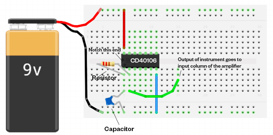
- First touch a wall or large metal object to remove static. Now insert the integrated chip (CD40106), with the notch on the chip at the left hand side.
- Do this by bridging the chip horizontally over the gap in the middle of the breadboard as shown on the previous page, carefully putting the top row of pins in one row and the bottom row of pins in another row. It’s fiddly, and you’ll need to bend the legs in a bit (not too much otherwise the chip might bounce out).
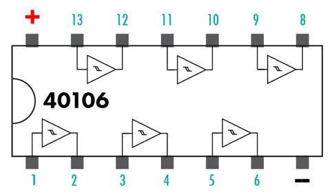
- Here’s a diagram of this chip (CD40106) – use it to refer to. The chip consists of 6 identical ‘inverters’ (the triangles) – without going into detail, they cause the circuit to ‘flip’ back and forth, generating a square wave.
- Now let’s do the most important thing – ‘ground’ the chip. Insert one end of a blue wire (or black wire) to a hole in the same column that the negative ‘-‘ pin of the chip (furthest right on the bottom of the chip) is in. Insert the other end of the wire into any hole on the very bottom row of the breadboard.
- Let’s connect the chip to where the positive end from the battery will later be connected. Insert a red wire into a hole in the same column that the positive ‘+’ pin of the chip (furthest left on the top of the chip) is in. Insert the other end of that wire into a hole in the very top row of the breadboard.
- Next, bend the legs of the capacitor outwards a bit. Put one leg of the capacitor in a hole of the same column as pin 1 of the chip (best to use the hole at the bottom of the column).
- Insert the other leg of the capacitor in one of the holes of the very bottom row of the breadboard.
- Now get the resistor and insert one leg into a hole in the same column as pin 1 of the chip (this is the same column where you put the first leg of the capacitor).
- Insert the other leg into the same column as pin 2 of the chip. If you look at the diagram of the chip, you will see that you’ve just completed the first ‘inverter’ circuit by connecting 1 & 2 with a resistor.
- Insert one end of another wire to the same column as pin 2 of the chip. This is your output wire. Connect the other end of that output wire to the INPUT column of your amplifier (in our one, this is row 15 – see the diagram in the ‘build your own amplifier’ worksheet).
- Connect the red wire from the battery to the very top row of the breadboard. Connect the black wire from the battery to the very bottom row of the breadboard. You will hear a sound – this is a ‘square wave’. Disconnect the battery and attach a different value resistor. Hear a different pitch?
Variations:
Replace the resistor with a potentiometer (pot) so that you can change the pitch with a dial: using the pot we recommend above, insert its three pins into separate unused columns to the left of the chip. Connect a wire from the same column as the middle pin of the pot to the column of pin 1 of the chip. Connect a wire from the same column as the right hand pin of the pot to the column of pin 2 of the chip. Now turn the dial and hear the pitch change. Create a ‘thin’ pulse wave by adding a signal diode between pin 1 and 2 of the chip (it only works one way, so if no sound comes out, swap the legs around).
This tutorial is part of the co:noise project, which has been funded by Arts Council England, FEAST, Cornwall Council, Penryn Town Council, Tea Social and Rapid Online. co:noise is a project designed to encourage people of all ages and musical backgrounds to make music. In this series of tutorials, we are providing instructions and ideas to make easy to build, low cost electronic instruments without needing to solder.
All components can be found on the Rapid Online website.


