
In this tutorial, you will learn how to build an easy to make, cheap battery powered amplifier. It will be made on what’s called a ‘breadboard’. You may need an adult to help you (and if you’re already an adult, well, you may need a child to help you). We have made a video to guide you through, and there are instructions below too (including a parts list) if you need extra help. Pause the video whenever you need to.
Before you start building the amplifier, you will need to understand what a breadboard is and how it works.
Breadboards:
Breadboards are used to learn how to build, design or test electronic circuits. The breadboard has strips of metal underneath the board, which connect the holes on the top of the board. The metal strips are laid out as shown below. Note that the top and bottom rows of holes are connected horizontally (and split in the middle on larger breadboards like this, which means they would need connecting to ensure the flow of electricity continues). The remaining holes are connected vertically, but have a gap in the middle where they are unconnected. Central columns such as B, C and D aren’t internally connected to each other. The wires show how they need connecting.

Learning electronics:
The best way to learn about electronics is with electronics books or kits, at school, or online. Search for ‘electronics for beginners’ on Google or YouTube and you should find some free tutorials. A common way to design and build circuits is by using ‘schematics’ – we won’t be using these here, but you can find out about them online.
What you need to know before you start building circuits:
- Safety first: always use batteries such as a 9V battery or a 4 x AA battery pack – this will always be safe. NEVER connect to a mains plug or plug socket in any way – it is very dangerous.
- Things might not always work first time and there could be a number of reasons why:
- Static from your clothes, nearby plastic, or even the carpet on a floor can cause an electronic chip to ‘fry’ (touching an electronic chip too much could damage it) – touching a wall or a big metal object before touching the circuit can help because it lets static charge escape to the ground
- If you make or alter a circuit while the battery is plugged in, you could damage electrical components – take the battery out before making any changes or if anything feels hot
- You might not have connected everything properly or put it in the correct row or column – always check the instructions, diagrams or connections –the other day I spent 20 minutes wondering why a very simple circuit wasn’t working before realising I had left out the most important part!
- A common mistake is not putting the battery wires in the correct row – check it!
- The battery might have run out – try swapping it for a new one (if you leave the battery in for too long, it can drain it, so only put it in when you are using or testing the circuit)
- Circuits contain lots of components with metal parts close together – check that the components aren’t touching each other (especially metal parts)
- Circuits and liquid don’t go well together – keep drinks away!
- It might not be the amplifier – check your instrument (is your instrument even connected properly?)
- Sometimes you just need another person to check it with you – ask someone to help
AND NOW….
How to make your own breadboard amplifier:
An amplifier connects the output of an electronic instrument to a speaker. This produces the volume (‘amplitude’). If your one stops working, here is how to build one. It’s fiddly and it may need a few attempts – if you are finding it difficult, ask a teacher or family member to help you. You may want to try a simpler circuit to understand how breadboards work (Google ‘how to make a simple LED circuit’). Practice makes perfect! Safety note: only use low power batteries such as a 9V battery – DO NOT connect it to a mains plug!
What you will need (electronic components available from rapidonline.co.uk):
- 1x breadboard – this is what you will put the components and wires in to make the circuit (available here or here)
- 1 x LM386 chip (available here)
- Capacitors: 1 x 220uF (black cylinder); 2 x 10uF (black cylinder); 1 x 0.047uF (small brown with ‘473’ printed on it); 2 x 0.1uf (small brown with 104 printed on them)
- Resistors: 1 x 10 ohm (you might see this as 10R); 1 x 10K (coloured that tell you the value – Google ‘resistor codes’ for help)
- 1 x small speaker (8 ohms)
- 1 x 9V battery and a battery clip (the battery clip will have black and red wires)
- Multiple wires (we recommend ‘jumper’ wires because these make breadboarding easier)
- 1 x electronic instrument for making a sound (e.g. a contact mic or a simple oscillator)
- 2 x crocodile leads to attach to the tabs of the speaker
Instructions:
- Here is a diagram of what you will be making. Keep referring to it. Some breadboards may differ – if yours has red (positive) and blue (negative) lines in the top and bottom rows, use those to connect the correct battery wires, and the negative speaker wire. We have put this circuit as far left as possible in case you want to put an oscillator instrument on the same breadboard (saves money and batteries!). Note that the blue capacitors are likely to be brown, and the resistors may be different in colour to the ones shown. In this diagram, we’ve put a ‘contact mic’ (the gold and silver disc) to demonstrate where the output wires from an instrument would go.

- Put the LM386 chip into the breadboard, with the ‘semi-circular notch’ on the left of the chip – (you may need to bend the legs). Here is a diagram of the LM386. Refer to this – it tells you what number the legs or ‘pins’ are.
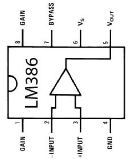
- Let’s continue by focusing on pin 5 of the chip (it’s on the top right of the chip). In the hole directly above pin 5, insert one leg of the blue 10 ohm (10R) resistor. Bend the other leg it so that it comes out to the right and down OVER the gap in the middle of the breadboard (like a bridge over a river) and into the lower column that is to the right of the end of the chip (see diagram) – in other words, it goes in a slightly diagonal direction. It will be useful here to now bend both legs of the resistor to the right, so that it is out of the way.
- In the hole directly below where you have placed the second leg of the resistor, put one leg of the 0.047uF capacitor. Put the other leg (you might need to do some bending) in the lowest row on the breadboard. This row is known as the ‘ground’ (on some breadboards it may be marked by a blue line or a negative ‘-‘ symbol).
- Look back at the column where pin 5 of the chip is. There are three holes remaining. Insert the long leg of the 220uF capacitor in one of these remaining holes in this column. Put the shorter leg of the 220uF capacitor in a hole in the most furthest right column on the breadboard. This is now your amplifier’s OUTPUT column.
- In that OUTPUT column, insert the ‘positive’ wire from the speaker (most speakers won’t come with wires attached – you will need to add a crocodile lead to the positive tab on the back of the speaker and connect that to a wire first, or ask an adult to solder a wire). Insert the negative wire from the speaker into a hole on the very bottom row of the breadboard (‘ground’) – again, attach a crocodile lead to the negative tab on the speaker, and attach a wire to the other end.
- Let’s go to pin 6 of the chip next. Get a small 0.1uF capacitor and stretch the legs out a bit. In the column above pin 6, insert one leg of this capacitor. From that hole, bring the other leg to the left and into an unused column to the left of the chip.
- In that same column, insert one end of a wire. The other end of that wire goes diagonally over the chip to a hole in the column where pin 4 of the chip is. We recommend the hole directly below pin 4.
- Put one end of a blue (or black) wire in another hole in the column below pin 4 of the chip. Connect the other end of that wire to the very bottom row of the breadboard (the ‘ground’).
- At the column where pin 6 of the chip is, insert a red wire. Put the other end into the top row of the breadboard (this row is known as ‘positive’ or ‘+’ and is marked with a red line on some breadboards).
- Get the other 0.1uF capacitor and stretch the legs. In the column above pin 7 of the chip, insert one leg of the 0.1uF capacitor. Bring the other leg out to the left, and into another completely unused column to the left of the chip. In that column, insert one end of a blue (or black) wire and add the other end of the wire to the very bottom row of the breadboard (the ‘ground’).
- The next component is a 10uF capacitor (the small black capacitor). This makes the amplifier much louder, and is optional. Add one leg of the 10uF capacitor to a hole in the column where pin 8 of the chip is. Add the other leg to a hole in the column where pin 1 of the chip is. We recommend this if you will be using a contact mic (a low volume instrument), but you may want to remove it if you’re using an oscillator instrument as it will be LOUD.
- Put one end of a blue wire in a hole in the column below pin 2 of the chip. Connect the other end of the wire to the very bottom row of the breadboard (the ‘ground’).
- Put one leg of the green 10K resistor in a hole in the column below pin 3. Put the other leg in an unused column to the left of the whole amplifier circuit. This same column is the amplifier’s INPUT. This will be where your instrument ‘s output (e.g. from a contact mic or an oscillator) will connect to. We’ve used column 15 on the lower half of breadboard.
Optional changes:
Volume control: You could add a volume control by changing the 10K resistor for a 10K potentiometer. This can be a bit tricky, so it is best to look up how to use a potentiometer as a volume control online. For now, simply remove the 10 ohm capacitor for a quieter volume, and keep it there for a louder volume.
This tutorial is part of the co:noise project, which has been funded by Arts Council England, FEAST, Cornwall Council, Penryn Town Council, Tea Social and Rapid Online. co:noise is a project designed to encourage people of all ages and musical backgrounds to make music. In this series of tutorials, we are providing instructions and ideas to make easy to build, low cost electronic instruments without needing to solder.
All components can be found on the Rapid Online website.


